This high performance stepper motor driver from SMD is based on modern hardware components and intended for motors with current per phase up to 8.0 A. This model is controlled via STEP/DIR signals or internal pulse generator with potentiometer speed regulation. Excellent dynamics and high torque at high speeds distinguish it from competitors. Smooth and silent motion can be achieved by using of a microstepping mode. Mounting the driver on a standard DIN rail makes it easy to place it in a production environment.
Please just get in touch to find out more!
 Stepper motor control methods:
-
Pulse position control
-
Analog speed control (built-in potentiometer)
Additional features:
-
Built-in braking resistor for high inertia load operation
-
Possibility to connect an external braking resistor
-
Automatic transition between current (with higher torque and better dynamics) and voltage (with smoother and quieter operation) phase commutation modes
-
Microstepping up to 1/128
-
Enable signal can be inverted if necessary
The fundamental difference between this driver and previous versions is the new design and improved circuitry, which provide very fast acceleration and maintain significant torque at high speeds. Acceleration to speeds of 1000 rpm or more can be done in a fraction of a second. Operating speeds in excess of 4000 RPM with enough torque to do useful work are now available for most stepper motor models.
Depending on the task set, the driver can be used in one of two control modes – pulse position control for solving positioning tasks, speed control with built-in potentiometer – for maintaining and regulating speed.
| TECHNICAL DATA | |
|---|---|
| Voltage | 24 - 48VDC |
| Max. current per phase | 1.0 - 8.0 A |
| Microstepping | 1/1 - 1/128 |
| Control methods | potentiometer, STEP/DIR |
| Size | 122x100x46 mm |
| Inputs STEP, DIR, ENABLE: | |
| High voltage level | 4 - 24 VDC |
| Low voltage level | 0 - 1 VDC |
| Input STEP resistance | 3 kOhm, no less |
| Inputs DIR and ENABLE resistance | 1 kOhm, no less |
| Input current of control input STEP | 1,4 - 4 mA |
| Input current of control inputs DIR и ENABLE | 4 - 12 mA |
| Output «FAULT» parameters: | |
| Signal type | opto-coupler output |
| Maximum voltage | 20 VDC |
| Maximum load current | 100 mA |
| Resistance at close contact | 100 Ohm, no more |
CONNECTION
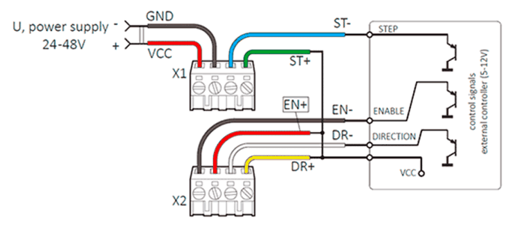
It is allowed to use as control signals with a voltage level of 24 V under condition, that additional current-limiting resistors of 1 kOhmis provided and connectedto the DIR and ENABLE inputs.24 V STEP signals can be used with an additional 3 kΩ current-limiting resistor.
Connecting the stepper motor driver SMD-8.0DIN ver.2. Example 1 – common cathode
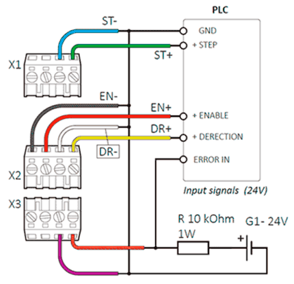
Connection of input and output signals of the driver. Example 2 – common anode
It is allowed to use as control signals with a voltage level of 24 V under condition, that additional current-limiting resistors of 1 kOhmis provided and connectedto the DIR and ENABLE inputs.24 V STEP signals can be used with an additional 3 kΩ current-limiting resistor. In the normal state of the driver, the FAULT output is closed to GND, but in the event of an abnormal situation, this circuit opens. The emergency stop of the motor is carried out by a signal at the ENABLE input of the level 0…1V (or 4…12V if the signal is inverted).
In the normal (working) state of the driver SMD-8.0DIN ver.2, there is a resistance 150-160 Ohm between the “FL +” and “FL-” terminals. LED VD1 is lit. In the event of an emergency, the resistance between the terminals tends to infinity, VD1 fades.